
An FTTH drop bore can be short and still leave little room for error. A Grundomat Boring Missile is one example of the pneumatic piercing tool class used to form small-diameter crossings beneath driveways, sidewalks, and other finished surfaces.
The distance may be only 20 to 50 feet. However, a few inches of departure can move the tool outside the receiving pit, reduce clearance from another utility, or force a larger recovery excavation. Once a conventional piercing tool fully enters the ground, the operator usually cannot steer it back onto line.
So how accurate is this method?
No published evidence supports one universal average. The strongest engineering guidance uses a conditional benchmark of 1% of bore length in horizontal line and vertical grade. That benchmark assumes stable ground and correct initial alignment. It is a planning reference, not a guaranteed field result.
The short answer
Pneumatic piercing can provide enough accuracy for a short FTTH drop when the route has four features:
- homogeneous, compressible soil;
- a carefully stabilized and aligned launch;
- a target corridor that allows several inches of departure;
- no unexposed critical utility within that corridor.
The method becomes harder to justify when mixed fill, cobbles, roots, saturated soil, or a narrow utility clearance controls the job. Tracking can show that the tool has moved off course, but it does not turn a conventional mole into a steerable system.
The practical question is not whether a tool is “accurate.” The contractor must ask whether the planned route can tolerate the uncertainty of an unsteered bore.
Accuracy means more than reaching the exit pit
Crews often judge a shot by one visible result: the tool entered the receiving pit. That result matters, but it does not describe the full path.
Four separate measurements define bore accuracy:
| Measure | What it tells you |
| Exit-point error | The horizontal and vertical distance between the planned and actual exit |
| Line and grade | Departure from the planned horizontal alignment and vertical profile |
| Path deviation | Movement anywhere between the launch and receiving pits |
| Repeatability | How consistently the same setup produces similar results over several bores |
A large receiving pit can hide a substantial exit error. It also cannot prove that the tool maintained clearance from an intermediate utility.
Tracking accuracy is another separate issue. A sonde and receiver estimate the tool’s location, depth, or pitch. Those readings do not directly measure the final conduit position, and they do not provide active steering.
What the 1% benchmark actually says
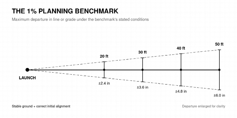
The Trenchless Technology Center’s Guidelines for Impact Moling states that an unsteered mole may remain within 1% of bore length in both line and grade when the ground is stable and the launch receives correct initial alignment. A 2022 City of Los Angeles specification also requires the selected tool to have 1% line-and-grade capability under proper operating procedures.
Converted into field dimensions, 1% produces the following departure in each plane:
| Bore length | 1% of bore length |
| 20 ft | 2.4 in |
| 30 ft | 3.6 in |
| 40 ft | 4.8 in |
| 50 ft | 6.0 in |
These values do not represent measured averages. Neither source publishes repeated trials, an error distribution, or a success probability. The benchmark also applies separately to horizontal and vertical departure.
The ground condition matters just as much as the number. Applying the 1% figure to mixed construction fill or cobbles removes one of the benchmark’s main conditions.
Small launch errors become large exit errors
Initial alignment controls the only part of the trajectory that the operator can directly correct. Once the tool body enters the ground, soil resistance takes over.
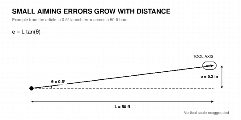
Basic geometry shows how quickly a small aiming error grows:
e = L tan(θ)
Here, e is the resulting offset, L is bore length, and θ is the launch-angle error.
| Launch-angle error | 20-ft bore | 30-ft bore | 40-ft bore | 50-ft bore |
| 0.25° | 1.0 in | 1.6 in | 2.1 in | 2.6 in |
| 0.50° | 2.1 in | 3.1 in | 4.2 in | 5.2 in |
| 1.00° | 4.2 in | 6.3 in | 8.4 in | 10.5 in |
A half-degree error creates about 5.2 inches of offset over 50 feet. That nearly consumes the full 1% planning allowance before the tool encounters a rock, soft pocket, or soil transition.
These calculations describe a straight path in uniform material. Real ground can increase, reduce, or redirect the final error.
The launch setup therefore needs more than approximate visual aiming. The cradle must remain stable, and the target must establish both line and grade. The Grundomat Model P operator’s manual instructs the operator to launch at reduced power and keep checking alignment until the tool enters completely. ITU-T Recommendation L.38 gives similar guidance for telecommunications duct and cable installations.
That launch sequence is trajectory control. Later actions are monitoring and recovery.
Soil determines whether the tool holds its line
An impact mole advances by displacing soil around its body. Uniform soil supplies reasonably balanced resistance. Variable ground does not.
The FHWA utility-cut manual warns that a mole in nonhomogeneous soil may follow the path of least resistance. Iowa SUDAS Chapter 14 also identifies rocks, boulders, and other obstructions as causes of deviation.
| Ground condition | Likely effect on an unsteered tool |
| Uniform clay or silt | Usually provides the most consistent directional support |
| Very soft or saturated soil | Can let the tool swim, oscillate, or lose forward grip |
| Loose sand or gravel | Can provide inconsistent support and allow the bore to collapse |
| Dense or dry material | Raises resistance and can cause slowing, refusal, or deflection |
| Mixed fill or an old utility trench | Creates changing resistance and a possible softer path |
| Cobbles, roots, concrete, or debris | Can produce a local course change, refusal, or tool damage |
| Solid rock | Generally falls outside conventional impact-moling applications |
None of these categories produces a guaranteed outcome. “Suitable for penetration” and “stable enough for a narrow accuracy tolerance” are different tests.
Launch and receiving pits also provide only two soil observations. Material between them may include previous trench backfill, landscaping fill, pavement base, roots, or demolition debris. A route can look uniform at both ends and still contain a deflection point.
What one independent field case shows
North American field studies rarely publish both the planned and measured path of an impact mole. One Iowa State University and InTrans report provides a useful, though limited, example.
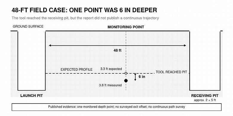
The project used a 2.5-inch Grundomat to install a 0.75-inch copper gas pipe over 48 feet. The report described black fat clay, a water table within three feet of the surface, and roughly four feet of cover. The crew dewatered both pits, placed the tool on a cradle, and used a telescopic aiming frame.
The tool reached a receiving pit measuring about 2 by 5 feet. At one monitoring location, however, the measured bore-center depth was 3.8 feet instead of the expected 3.3 feet. The difference was six inches.
This field report does not publish a surveyed exit offset or a continuous trajectory. It also covers one gas-line installation, not an FTTH trial. The report contains an unresolved inconsistency between the monitored bore-center depth and a later statement about the installed pipe depth.
The case therefore cannot establish a typical error rate. It does show why arrival inside a large pit does not prove that the underground path matched the planned profile.
Longer shots increase uncertainty
Longer bores amplify launch-angle error and expose the tool to more ground. They also reduce the crew’s ability to divide a difficult route into separately aligned sections.
Published practical ranges vary:
- The Trenchless Technology Center describes about 35 feet as a typical nonsteerable single run.
- Iowa SUDAS gives 40 to 60 feet as a typical practical range before inaccuracy and lack of directional control become limiting.
- The HammerHead operator’s manual describes holes up to 50 feet.
- TT Technologies markets Grundomat bores from 50 to 150 feet.
These figures do not measure the same thing. A claimed achievable length is not an accuracy tolerance, and a successful long bore does not establish repeatability.
Advance speed also needs a model-specific interpretation. The Grundomat Model P manual identifies excessive speed as a possible cause of deviation for that tool. Older general guidance reports a much broader range across impact-moling equipment. Soil, diameter, head design, air supply, and tool condition all affect those numbers.
Crews should watch changes in behavior rather than chase one universal production rate. Unexpected acceleration can indicate weak support. Sudden slowing can signal dense material or an obstruction. Either change should trigger a check against the project’s stop criteria.
Tracking detects deviation but does not correct it
A sonde can help a crew identify the tool’s position, depth, or pitch. That information can support a decision to stop, reverse, excavate, or abandon a bore.
Sonde position affects how early the crew sees a change. A front-mounted sonde represents tip behavior sooner but must withstand direct impact forces. A rear-mounted sonde follows the head, so it can reveal a deflection later.
Neither arrangement actively changes the path of a conventional piercing tool. The Iowa field report states that the crew could no longer steer after the tool fully entered the ground. ITU guidance recommends recovery actions such as stopping, backing out, excavating to the tool, or relaunching when the bore departs from line.
No independent study located for this review quantified front- versus rear-sonde position error while a pneumatic tool was hammering. Tracking improves visibility. It does not justify a tighter design tolerance by itself.
Head design claims need independent testing
Manufacturers use several head designs to improve penetration and directional stability. TT Technologies states that the reciprocating stepped head on a Grundomat helps the tool stay on target. Vermeer makes a similar accuracy claim for moving-head options on selected hole hammers.
The available independent guidance does not rank fixed, moving, and reciprocating heads through matched field trials. It also notes that each design can deflect when it meets an intrusion or a sharp change in resistance.
Contractors should match the head to documented soil conditions and follow the manual for the exact model. They should not treat a design claim as a measured percentage improvement.
Tool condition also matters. The Grundomat manual lists a worn multi-cutter cone, the wrong displacement head, poor initial alignment, swimming, and excessive advance speed among possible causes of deviation. A surface function test can confirm that a used tool cycles and reverses. It cannot prove underground accuracy.
Set the corridor before selecting the method
Start with the permitted error in inches. Define separate horizontal and vertical limits, then apply them to the full underground path.
For example, a 40-foot crossing with only three inches of permitted exit error allows a geometric launch error of about 0.36 degrees. That calculation assumes a straight tool and ignores soil-induced movement. The real launch tolerance must therefore be tighter.
An unsteered pneumatic tool is generally easier to justify when:
- the shot is short and straight;
- cohesive soil appears uniform along the route;
- the exit target allows several inches of departure;
- the crew can expose critical utility crossings;
- the plan includes safe reversal, recovery, or relaunch options.
A guided or steerable method provides a stronger fit when:
- the required error falls materially below the conditional 1% benchmark;
- exact depth matters throughout the route;
- mixed fill, cobbles, debris, or major soil transitions are likely;
- a critical utility occupies a narrow clearance corridor;
- the route is long and offers no intermediate access;
- the consequence of a miss is high.
This screen does not make the decision automatically. Local requirements, tool diameter, conduit configuration, soil investigation, and the contractor’s approved procedure still control the job.
Utility risk changes the accuracy requirement
An accuracy estimate cannot replace utility exposure. OSHA 29 CFR 1926.651 requires employers to determine the estimated location of underground installations before excavation. As work approaches an installation, the employer must determine its exact location by safe and acceptable means.
Cross-bore history explains the concern. A PHMSA and NAPSR meta-analysis collected 26 responses representing 24 states. Seventy percent of respondents recognized pneumatic piercing as a cross-bore threat. Fourteen of 23 responding states reported cross-bore incidents or near misses involving sewer systems.
Those findings cover utility construction broadly. They do not measure FTTH bore accuracy. They do show why a successful exit cannot prove safe clearance from an unexposed lateral.
Local rules can also be much stricter than general performance guidance. Los Angeles requires crews to expose utility crossings, limits observation-pit spacing to 30 feet, and requires front locating equipment for lines larger than two inches. Its half-inch deviation threshold triggers abandonment and restart. These requirements apply locally, not nationwide.
A practical control sequence
The following sequence combines public engineering guidance, telecommunications guidance, municipal requirements, and manufacturer instructions:
- Define acceptance limits. Set maximum horizontal and vertical departure for the exit and the full path.
- Locate and expose utilities. Confirm critical crossings and private services instead of relying only on surface markings.
- Check the route. Record soil, moisture, pavement structure, roots, fill, and signs of previous trenches.
- Calculate alignment sensitivity. Convert the permitted exit error into a maximum launch-angle error.
- Match the tool to the route. Confirm diameter, head, reverse system, sonde arrangement, conduit attachment, air supply, and current model instructions.
- Build a stable launch. Secure the cradle, establish an independent target, launch at reduced power, and recheck line and grade until the tool enters fully.
- Monitor behavior. Track position where available and watch for unexpected speed, slowdown, swimming, refusal, or loss of signal.
- Apply stop criteria. Reverse, expose, recover, or relaunch according to the approved plan when readings or behavior exceed the defined limits.
- Verify the result. Record the exit location, conduit condition, and as-built depth where project risk requires it.
The project team must adapt this sequence to the exact tool manual and local rules. It does not replace an approved construction or safety procedure.
Appropriate does not mean precise
Pneumatic piercing tools can fit short FTTH drop crossings because they form a small bore without opening a continuous trench. Their accuracy still depends on a narrow set of conditions.
The 1% figure offers a useful conditional benchmark. It does not describe an average bore, a success rate, or a warranty. A careful launch can still meet variable ground, and a tracked tool remains unsteered.
Use pneumatic piercing when the route can tolerate that uncertainty. When the permitted corridor is narrow or the consequence of deviation is high, active guidance provides a more defensible control method.
Inside Telecom provides you with an extensive list of content covering all aspects of the Tech industry. Keep an eye on our Press Releases section to stay informed and updated with our daily articles.